- 您现在的位置:买卖IC网 > Sheet目录335 > ISL97634IRT26Z-TK (Intersil)IC LED DRIVR WHITE BCKLGT 8-TDFN
ISL97634
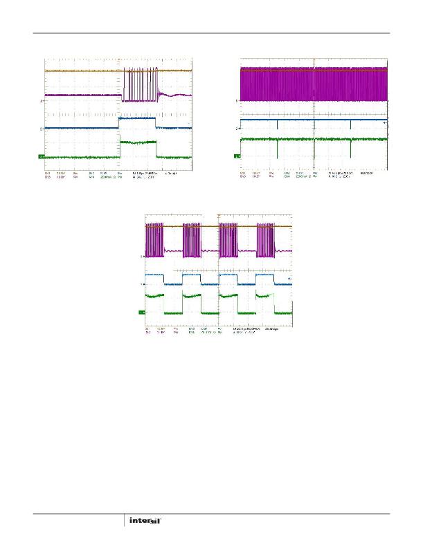
Typical Performance Curves (Continued)
V OUT
V OUT
LX
LX
PWM/EN
V IN = 4V
PWM/EN
ILED
R 1 = 4 Ω
L 1 = 22μH
ILED
V IN = 4V
R 1 = 4 Ω
L 1 = 22μH
FIGURE 8. PWM DIMMING AT 1kHz, D = 1% ZOOM IN
FIGURE 9. PWM DIMMING AT 1kHz, D = 99%
V OUT
LX
R 1 = 4 Ω
V IN = 4V
L1 = 22μH
PWM/EN
ILED
FIGURE 10. PWM DIMMING AT 20kHz, D = 50%
I LED = --------------- (EQ. 1)
I LED-AVG = --------------- ? D
Detailed Description
The ISL97634 uses a constant frequency, current mode
control scheme to provide excellent line and load
regulation. There are three OVP thresholds set at 14V, 18V
and 26V respectively. The ISL97634 operates from an input
voltage of 2.4V to 5.5V and ambient temperature from -40°C
to +85°C. The switching frequency is around 1.45MHz and
allows the driver circuit to employ small LC components. The
peak forward current of the LED is set using the R SET resistor.
In the steady state mode, the LED peak current is given by
Equation 1:
V FB
R SET
PWM Dimming
The ISL97634’s PWM/EN pin can be tied permanently to high
for a fixed current operation. On the other hand, the ISL97634
6
can be applied with an external PWM signal to pulse width
modulated output current. It is well understood that the LED
brightness is a linear function of the LED current. In addition,
the average LED current corresponds to the duty cycle “D” of
the PWM signal as shown in Equation 2:
V FB
(EQ. 2)
R SET
As a result, PWM signal provides a means to dim the LED
brightness. PWM dimming offers the best LEDs matching over
DC dimming. It is because the LED peak current operating
point is far away from the knee of the diode I-V curve where
part to part variations are high. The PWM dimming test results
are shown in Figure 7 with two PWM frequencies, 1kHz and
20kHz. The vertical scale parameter FB is proportional to the
current and therefore the brightness.
For the ISL97634, PWM dimming provides linear dimming
adjustment with low frequency signal, such as 1kHz and
below. The applied PWM dimming signal can be up to 32kHz;
FN6264.4
August 27, 2013
发布紧急采购,3分钟左右您将得到回复。
相关PDF资料
ISL97635AIRZ
IC LED DRVR WHT/RGB BCKLGT 24QFN
ISL97635IRZ
IC LED DRVR WHT/RGB BCKLGT 24QFN
ISL97636AIRZ
IC LED DRIVR WHITE BCKLGT 24-QFN
ISL97636IRZ-TK
IC LED DRIVR WHITE BCKLGT 24-QFN
ISL97671AIRZ
IC LED DVR PWM CTRL 6CH 20QFN
ISL97672AIRZ
IC LED DRVR LOW DIMMING 20QFN
ISL97672BIRZ
IC LED DRVR BACKLIGHT 20QFN
ISL97675IRZ-TK
IC LED DVR PWM CTRL 4CH 20QFN
相关代理商/技术参数
ISL97635AIRZ
功能描述:IC LED DRVR WHT/RGB BCKLGT 24QFN RoHS:是 类别:集成电路 (IC) >> PMIC - LED 驱动器 系列:- 标准包装:1 系列:- 恒定电流:- 恒定电压:- 拓扑:PWM,切换式电容器(充电泵) 输出数:1 内部驱动器:是 类型 - 主要:背光 类型 - 次要:白色 LED 频率:642kHz 电源电压:2.7 V ~ 5.5 V 输出电压:5V 安装类型:表面贴装 封装/外壳:10-VFDFN 裸露焊盘 供应商设备封装:10-VSON 包装:剪切带 (CT) 工作温度:-30°C ~ 85°C 产品目录页面:1371 (CN2011-ZH PDF) 其它名称:BD1603NUV-E2CT
ISL97635AIRZ-T
功能描述:IC LED DRVR WHT/RGB BCKLGT 24QFN RoHS:是 类别:集成电路 (IC) >> PMIC - LED 驱动器 系列:- 产品培训模块:Lead (SnPb) Finish for COTS
Obsolescence Mitigation Program 标准包装:2,500 系列:- 恒定电流:- 恒定电压:- 拓扑:升压(升压),切换式电容器(充电泵) 输出数:1 内部驱动器:是 类型 - 主要:背光 类型 - 次要:白色 LED 频率:625kHz ~ 875kHz 电源电压:2.7 V ~ 5.3 V 输出电压:5V 安装类型:表面贴装 封装/外壳:10-TFSOP,10-MSOP(0.118",3.00mm 宽) 供应商设备封装:10-µMAX 包装:带卷 (TR) 工作温度:-40°C ~ 85°C
ISL97635AIRZ-TK
功能描述:IC LED DRVR WHT/RGB BCKLGT 24QFN RoHS:是 类别:集成电路 (IC) >> PMIC - LED 驱动器 系列:- 产品培训模块:Lead (SnPb) Finish for COTS
Obsolescence Mitigation Program 标准包装:2,500 系列:- 恒定电流:- 恒定电压:- 拓扑:升压(升压),切换式电容器(充电泵) 输出数:1 内部驱动器:是 类型 - 主要:背光 类型 - 次要:白色 LED 频率:625kHz ~ 875kHz 电源电压:2.7 V ~ 5.3 V 输出电压:5V 安装类型:表面贴装 封装/外壳:10-TFSOP,10-MSOP(0.118",3.00mm 宽) 供应商设备封装:10-µMAX 包装:带卷 (TR) 工作温度:-40°C ~ 85°C
ISL97635AIRZ-TKR5306
制造商:Intersil Corporation 功能描述:
ISL97635IRZ
功能描述:IC LED DRVR WHT/RGB BCKLGT 24QFN RoHS:是 类别:集成电路 (IC) >> PMIC - LED 驱动器 系列:- 产品培训模块:Lead (SnPb) Finish for COTS
Obsolescence Mitigation Program 标准包装:2,500 系列:- 恒定电流:- 恒定电压:- 拓扑:升压(升压),切换式电容器(充电泵) 输出数:1 内部驱动器:是 类型 - 主要:背光 类型 - 次要:白色 LED 频率:625kHz ~ 875kHz 电源电压:2.7 V ~ 5.3 V 输出电压:5V 安装类型:表面贴装 封装/外壳:10-TFSOP,10-MSOP(0.118",3.00mm 宽) 供应商设备封装:10-µMAX 包装:带卷 (TR) 工作温度:-40°C ~ 85°C
ISL97635IRZ-T
功能描述:IC LED DRVR WHT/RGB BCKLGT 24QFN RoHS:是 类别:集成电路 (IC) >> PMIC - LED 驱动器 系列:- 产品培训模块:Lead (SnPb) Finish for COTS
Obsolescence Mitigation Program 标准包装:2,500 系列:- 恒定电流:- 恒定电压:- 拓扑:升压(升压),切换式电容器(充电泵) 输出数:1 内部驱动器:是 类型 - 主要:背光 类型 - 次要:白色 LED 频率:625kHz ~ 875kHz 电源电压:2.7 V ~ 5.3 V 输出电压:5V 安装类型:表面贴装 封装/外壳:10-TFSOP,10-MSOP(0.118",3.00mm 宽) 供应商设备封装:10-µMAX 包装:带卷 (TR) 工作温度:-40°C ~ 85°C
ISL97635IRZ-TK
功能描述:IC LED DRVR WHT/RGB BCKLGT 24QFN RoHS:是 类别:集成电路 (IC) >> PMIC - LED 驱动器 系列:- 产品培训模块:Lead (SnPb) Finish for COTS
Obsolescence Mitigation Program 标准包装:2,500 系列:- 恒定电流:- 恒定电压:- 拓扑:升压(升压),切换式电容器(充电泵) 输出数:1 内部驱动器:是 类型 - 主要:背光 类型 - 次要:白色 LED 频率:625kHz ~ 875kHz 电源电压:2.7 V ~ 5.3 V 输出电压:5V 安装类型:表面贴装 封装/外壳:10-TFSOP,10-MSOP(0.118",3.00mm 宽) 供应商设备封装:10-µMAX 包装:带卷 (TR) 工作温度:-40°C ~ 85°C
ISL97636AIRZ
功能描述:LED照明驱动器 6-CH LED DRVR RoHS:否 制造商:STMicroelectronics 输入电压:11.5 V to 23 V 工作频率: 最大电源电流:1.7 mA 输出电流: 最大工作温度: 安装风格:SMD/SMT 封装 / 箱体:SO-16N
